Diagnosing automotive intoxication in a Chevy Avalanche

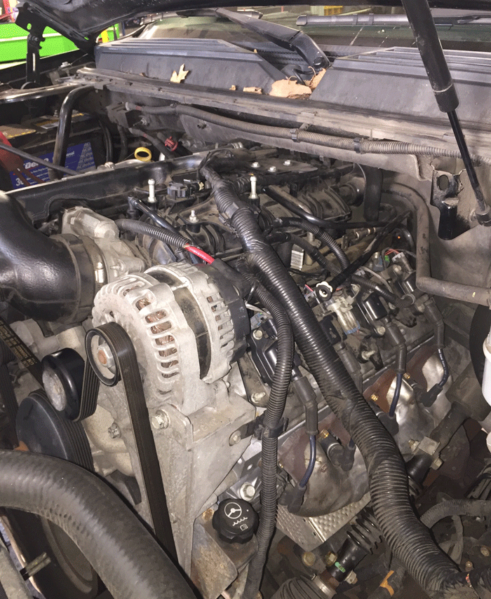
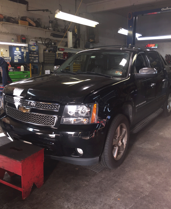
John Anello[/caption] Posted By: Albert B Hammond – Written By:John Anello Just when I thought I’d seen everything there is to see! A 2008 Chevy Avalanche (Figure 1), with a 5.3 liter automatic engine, was setting codes P0172 and P0175 (System rich, banks 1 and 2). This vehicle, which had 94,000 on the odometer, had this problem for well over a year according to the vehicle owner and there were times the spark plugs would foul to a point where the engine would experience an engine misfire. The fix at that point was to pull the spark plugs, replace them, clear the codes and head down the road for another few months. The shop had already replaced the MAF sensor and a suspected #1 injector thinking the rich condition was being caused from a shift in MAF calculations or a leaky injector on the #1 cylinder.  This however did not resolve the customer’s ongoing issue.

Figure 1

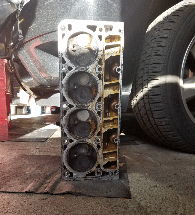
The owner of the vehicle was very anxious to get the car resolved especially with an overdue inspection sticker on the windshield. The truck was not running well, and he thought he now had cylinder head problems because of all the carbon buildup from the prolonged rich operation and add to the fact that many people had told him that these trucks were known for bad valve guides. All the avenues had been exhausted trying to  resolve his problem so he convinced the garage to perform a valve job on his truck. The garage was against it but the customer was persistent and willing to foot the bill so the cylinder heads were pulled to have a valve job done. The heads were visually examined and the shop was able to see the carbon buildup on the #1 cylinder but the other 3 cylinders on the same head did not seem bad (Figure 2). The spark plugs that came out of the engine did have black carbon on them but the #1 cylinder showed heavier deposits. The shop sent the cylinder heads out for repair and by later in the week the truck was reassembled and released to the customer.

Figure 2

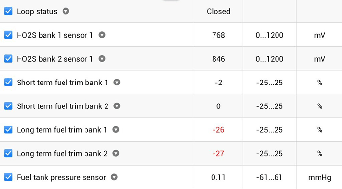
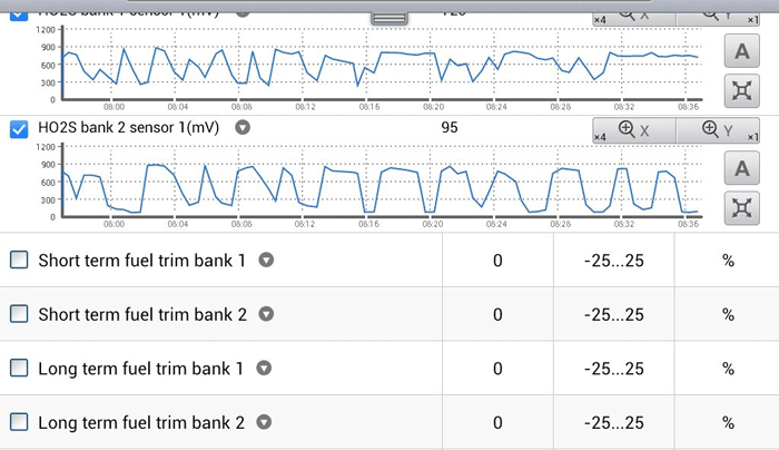
Well, that didn’t work. The valve job did not resolve the issue and the customer was soon back within a week with the CEL lamp on again. At this point I was now thrown into the mix to unravel the shop’s dilemma. When I arrived at the shop I hooked up my scan tool to check the fuel trims with the engine fully warmed up. This would give me an indication of what the ECM was actually doing to control the fuel. The engine was not running smooth and it had a slight rough idle. The Long Term Fuel Trims were down around negative 26 and yet both the upper O2 sensors were still seeing a rich operation (Figure 3). The ECM was having a hard time in acheiving O2 switching.  The whole concept of fuel control is to achieve a constant high to low switching state above and below 500 mv. The Short Term Fuel Trim will constantly move inversely l to the O2 sensor. When the O2 goes low the Short Term will go positive. When the O2 goes high the Short Term will go negative. The Short Term will eventually drive the Long Term Fuel Trim slowly to a final acceptable value of plus/minus 5 percent to 10 percent. Once the Long Term trims exceeds plus/minus 15 percent the ECM will usually set a code on most systems.  I pulled the brake booster line to see if the O2 sensors would respond to a major lean condition to rule out O2 sensor failure and their readings did go below 500 millivolts. At this point I was convinced that excess fuel was coming from somewhere or the truck had a sensor that was out of range.

Figure 3

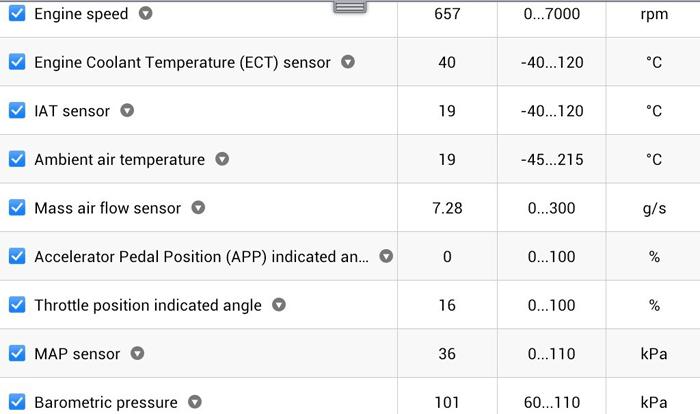
Figure 4

I next viewed some basic raw data with the engine running such as coolant and air temperature, Mass Air Flow, Throttle Position, Accelerator Position, Manifold and Barometric Pressures to see if everything was reading within reason (Figure 4). At idle, I typically expect 1 gram per liter of engine displacement per second for the MAF reading. This was a 5.3L  engine, so the 7 g/sec at idle was not too far off and the other sensors all seemed to be within spec.  I was looking for something that could really add some fuel such as leaky injectors, high fuel pressure or a leaky purge valve. So I first disconnected the purge valve line at the left side of the engine just above the ignition coils (Figure 5) but this did not have any effect on the rich operation. I even placed a fuel pressure gauge on the rail and measured the pressure, finding it within the spec of 60P.S.I. and when I turned the engine off the fuel pressure held without any signs of leakdown.
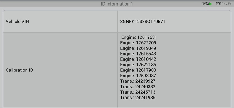
  I was puzzled to how this engine was getting more fuel then it could handle. I had to start thinking out of the box to find something out of the ordinary.  I did run across a vehicle a while back where a shop replaced a 5.3L ECM with a used 6.0L ECM. Both ECMs had the same hardware numbers but different software and the engine ran but was being over fueled. I pulled up the ECM info on the scan tool (Figure 6) but the VIN and software for this vehicle was correct. My next thought was to try and reset the Fuel Trims back to zero just in case the ECM was correcting for an old problem that was no longer there. Simply clearing codes or disconnecting a battery does no always guarantee resetting the fuel trims. Many learned adaptations can be stored in a Non-Volatile Memory than can only be reset using a scan tool function. I proceeded to the Fuel Trim Reset function in the scan tool and reset the learned fuel trims back to zero. I ran the vehicle and the upper O2 sensors were still seeing a rich condition so the ECM began to ratchet down the trim values again. This car had something unusual going on and it all pointed to a possible Engine Control Module issue but I wasn’t too quick to just go ahead and try one.

Figure 6

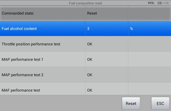
What was I facing? I had to venture out on the internet hoping that someone out there had a piece of the puzzle to this head scratching issue. My diagnostic paths of approach kept hitting dead ends without any reasonable clues to grow on. We live in a cyber world where information is now at our fingertips so I opted to Google my problem. I came across an issue about a Flex Fuel problem where you had to go in and reset the Flex Fuel alcohol counter if the ECM calculation was flawed somehow. I was unaware that this truck was Flex Fuel so it was not something I would have even given thought in my diagnostic process. I went back into the scan tool to dig for the feature and there it was – “Fuel Compensation Reset.” I proceeded to the function screen and was in shock to see a calculated Fuel Alcohol Content of 73 percent! How was it that this vehicle was calculating 73 percent alcohol mixture? How was this abnormally high reading possible if the owner never used anything but straight up gas? Did he accidentally pull up to an E85 station and fill up with the wrong stuff? Was this some type of driverless vehicle that went out on the town for for a night of drinking? There are many unanswered questions here but by simply resetting the alcohol content back to 3 percent default (Figure 9) and resetting the fuel trims again the vehicle was back in fuel control and ran like a champ (Figure 10)! Now I needed answers as to how this counter had gotten so high in the first place.

Figure 9

Figure 10

The Flex Fuel vehicles have been around since the late 90s and are designed to handle the 85 percent alcohol to 15 percent gas mixture. The alcohol used is an ethanol made primarily from corn but it can also be made from a variety of starch or sugary crops including potatoes, sugar cane, beets or even organic cabbage. Vehicles using E85 usually have specially lined gas tanks and have fuel system components that can handle the alcohol. The claim is you get a little more torque and horsepower and higher Octane ratings of up near 105. The alcohol does burn cooler and cleaner than gasoline. The downside is that you will need more of a gas mixture in colder climate that can vary from 25 percent to 30 percent mix of gas to aid in cold weather starting. Also alcohol has a lower BTU rating than gasoline so the fuel air ratio has to be bumped down from the norm of 14.7-1 to a low of 9.7-1 thus the reason why an onboard controller has to run a richer mixture and as a result your gas mileage is lower. Most cars since 1995 without Flex Fuel can handle 10 percent alcohol in their system because they are built to handle it but put that amount of alcohol in an older car and you’re asking for trouble that can lead to corroded components, damaged seals or severe fuel pump/engine damage. Today’s non Flex Fuel cars can handle up to 15 percent alcohol. This gives the gas companies more reason to “Stretch the Soup” just to meet their needs. Pulling up to a gas station today be sure to read the warning of alcohol content in the gas you buy (Figure 11). It would be nice if the fueling station would just offer you an option at the pumps to have a shot of alcohol to drink or just have you directly place it in your tank. There are some countries such as Brazil that will use a full concentration E100 alcohol for their specially designed vehicles where cold starting issues are not a factor. They will usually denature the mix with 2 percent of gas or Iso-propyl to keep people from trying to drink it!

Figure 11

This Avalanche does not use a direct Flex Fuel sensor to measure the alcohol content but rather Fuel Trim algorithms to adjust the alcohol calculation. If this truck were ever to experience a lean condition the ECM could easily mistake the lean condition for an increase of alcohol in the gas and miscalculate the mixture. When filling the tank with E85 you are supposed to do it on a warmed up engine ONLY and after a fill up you are supposed to drive the vehicle a minimum of seven miles to recalculate the mixture. If you fill the tank and immediately park the car and let it sit for too long the ECM with calculate the mixture on warmup the next key cycle and cause a higher than normal alcohol mixture content value. I can tell you that the owner had this problem since the day he purchased the vehicle from a lot in Pennsylvania and he lives in New Jersey. I did a Google search and there are about 2,758 E85 filling stations in the US and most are concentrated in the middle of the U.S. and there are only a few in Jersey. The prior owner did leave a couple of clues behind, though. He left a ski rack on the roof of the truck and never deleted his trips in the navigation system that revealed some extensive driving in Colorado, North Dakota, Minnesota, Michigan and Nova Scotia and he had access to many E85 stations because his travels were centralized in the “Corn Belt” states. It would be hard for me to believe that an ECM could calculate 73 percent alcohol from bad driving habits or prior lean conditions. I’m thinking the original owner was very fond of his Flex Fuel vehicle on his ski journeys across the US and possibly was the culprit to adapting his truck to be a compulsive alcoholic. It’s just beyond me how the vehicle was unable to adapt back to non E85 gas. Just when you think your game plan is set in stone to resolve a simple rich condition that you may have conquered many times in the past along comes a curveball of events that just is mind boggling. This is why I love this business. You just never stop learning. Hope this story hits home with you fellow technicians out there. Article Source: http://www.searchautoparts.com/automechanika-chicago/commitment-training/diagnosing-automotive-intoxication-chevy-avalanche?page=0,1#sthash.yX8uyyYT.dpuf ]]>

Your cars heating and cooling system – The Heater Core

Like the human heart, the heater core is the center of your cars circulatory system with large veins entering and exiting and small vessels inside. The life blood of your heating system is your vehicle’s coolant.

The heater core, which is located in the dashboard of your car, is really a miniaturized radiator. The heater core is used in heating the cabin of a vehicle. Hot coolant from the vehicle’s engine is passed through a winding tube of the core, a type of heat exchanger between coolant and cabin air. Fins attached to the core tubes serve to increase the surface for heat transfer to air that is forced past them, by a fan, thereby heating the passenger compartment.

What can go wrong with the heater core?

The heater core is made up of small piping that has numerous bends. Due to the size of the tube winding through the heater core any debris in your cooling system will end up clogging your heater core. Over time, dirt and other contaminants can build up in the coolant, or it may become acidic corroding the cooling system components themselves. Clogging of the piping may occur if the coolant system is not flushed or if the coolant is not changed regularly.

If clogging occurs the heater core will not work properly. Control valves may also clog or get stuck. Once clogged, the hot coolant can’t pass through the heater core, resulting in no heat for the cabin or defrost for the windshield

Another possible problem is a leak in one of the connections to the heater core. Electrolysis can cause excessive corrosion leading to the heater core rupturing. Coolant will spray directly into the passenger compartment followed by white colored smoke, a significant driving hazard.

Self-Diagnosis:

Engine coolant has a very distinctive sweet/oily smell. If you notice this smell inside your car, check for dampness around the passenger side floor/footwell. If you find wetness, you probably have a leaking heater core. A related symptom is a sticky film coming out of the defroster ducts and settling onto the windshield. This is one of those problems that starts out small and gets worse over time, so the sooner you can get it fixed, the better especially if it’s during winter time.

Like heart surgery heater core replacement should be left to the specialists

The heater core is usually located under the dashboard inside of the vehicle and is enclosed in the ventilation system’s ducting, servicing it often requires disassembling a large part of the dashboard. Removing your dash is not a job you want to leave to just anyone. Repair Pal estimates the labor cost to replace a heater core to be between $550 to $700 or about 5.5 to 7 hours of an experienced mechanics time. Find a shop the specializes in replacing heater cores. 

What to do to prevent a “heart attack”?

If you are not experiencing any symptoms of a damaged heater core now is the time to act to help avoid a problem in the future. Car manufacturers recommend that you change the radiator fluid in your vehicle every 24,000 to 36,000 miles or every 24 to 36 months. However, your personal driving habits will also determine the frequency of needed radiator fluid changes. If you drive your vehicle in extremely hot temperatures like we had in Reno last summer, you may want to consider changing the fluid once a year or every 12,000 to 15,000 miles.

Also, you can unscrew the pressure cap and look at the liquid inside the reservoir or radiator, depending on the type of system you have. Coolant can be green, greenish yellow, orange, red, or blue, but is the liquid clear, or is stuff floating around in it? Does it look rusty? If the answer to either question is yes it’s time for a cooling system service.

If you are past the recommended mileage or your coolant looks funky you should consider the manufacturer’s recommended cooling system maintenance service at a trusted shop in your area. If you are having any concerns about your cooling system, experiencing any symptoms of a damaged heater core, or just lack of heating you should take it to your local trusted shop for a heating system diagnostic testing.

]]>
The importance of buying the right tires for your car

If you have never had to change the tires on your vehicle before, it can feel like quite a challenge if you don’t know what tires your vehicle needs. There are many factors to consider when it comes to changing your tires including price, brand, comfort, appearance, and safety: things that should all be on your checklist. If your car was brand new when you bought it, it is likely that the tires you need are the same as the ones you had to start with. This makes the job fairly simple; as you know which tires you need, the only other job you need to do is find someone reliable to fit them for you. Different vehicles are fitted with different types of tires that are specific to each vehicle. Factors depending on where you live, your typical weather conditions and terrain will all affect the type of tire that you need so it is important to ask a specialist about your tires, as they can advise you depending on all of the above factors. The cost of your new tires will very much depend on your vehicle and tire type. If it was used when you bought it, you may be able to find the name of your tires in your handbook. If you don’t have that information, it is a good idea to do your research before you jump into anything. You can find information from a local dealership or even through the internet. It is also important to check the tires when you buy a used car, as the vehicle could be fitted with the wrong tires so it is a good idea to replace them quickly with the correct tires. Knowing what tires you need is also important because it helps you for the next time you need to change them, meaning you can get replacement tires quickly. There are exceptions, however; some vehicles allow you to have different types of tires. It is important that you research beforehand and that you know for certain that they can be fitted to your vehicle safely. Your tires should be replaced when the tread falls below the legal minimum. In the U.S Most states require a minimum of 2/32 of an inch (approximately 1.6 mm) of tread. If you are pulled over by the police and they are below the minimum legal tread depth you could end up with points on your license and a fine. If they are not up to the standard it will also mean that your vehicle will fail its yearly inspection where it’s required by law. It is important that you carry out regular checks on your tires to make sure that they are in the best condition. These checks can be carried out at home and involve looking for bulges, scratches, general wear and tear and even objects that could have punctured the tires such as sharp stones or nails.]]>

Automotive Repair Is Inevitable, But These Tricks Can Help

Automotive repair is inevitable, even for newer cars with less mechanical issues. For those who own older cars, routine maintenance is vital in avoiding major automotive repairs. Once a major part or system in the vehicle needs repairs, it could cost hundreds or even thousands of dollars to get back on the road again.  A good way to avoid expensive automotive repairs is to have a trusted mechanic who is familiar with your car. Having a good mechanic on your side can be very helpful when it comes to regular maintenance because they are familiar with your car’s needs and can provide good preventative maintenance. Good preventative maintenance can help prevent a major breakdown. Furthermore, your repairs might be a little less expensive if there is a breakdown because a regular mechanic can more easily figure out the cause. There are many different automotive repair shops you can choose from and finding a mechanic shouldn’t be that difficult. However, finding a trustworthy mechanic’s shop that can do quality work is key. There are a few techniques and tips you can employ in order to find a good mechanic.  The most important thing to remember when looking for a good mechanic to perform affordable quality work is to never wait until you have a vehicle breakdown to find an auto mechanic. This is one of the biggest mistakes a vehicle owner can make because, in the event of a major breakdown, they panic and simply hire the first mechanic they find in the phone book or online to diagnose and fix the vehicle. Many times, the repairs can cost more because the vehicle owner does not have the time to shop around for an affordable mechanic. If you look for a mechanic ahead of time, you are more likely to find one who is both skilled and more affordable. Finding a mechanic through word-of-mouth recommendations is one of the best ways to find a good mechanic. If you have a friend with an older car that runs well, you can find out who their mechanic is to begin the search for an auto repair shop. If you cannot find an auto repair shop through direct word-of-mouth recommendations, you can check you local listings online. Searching online can be helpful because mechanic listings online will also include customer reviews that will give you a better idea of who well that particular shop or mechanic can service your car. You can also educate yourself on automotive repair in order to avoid major problems and to have more knowledge on automotive repair. Automotive education can help you to better understand preventative car care needs in order to avoid major repairs. Furthermore, when you take your car to a mechanic for servicing you will have the advantage of knowing if the mechanic is credible, simply by knowing what type of issues your car has.  Automotive repair can be expensive, but some of this expense can be avoided if you have a good mechanic that can perform regular preventative maintenance. ]]>

Electrical Testing and Troubleshooting Tips With Vince Fischelli

This is a re-post from Motor Age youtube channel.

Enjoy

https://youtu.be/mVJWuZ6XrwA
Published on Mar 1, 2013

In this edition of “In The Workshop”, Motor Age technical editor sits down with Vince Fischelli, president of Veejer Enterprises in Garland, Texas. Vince is a nationally recognized expert in automotive electrical troubleshooting techniques and has made learning them at home easy to do with his easy-to-use test boards. Learn how three simple measurements will quickly lead you to the problem area and how Vince’s training method can benefit you!

Visit the website at http://www.veejer.com Click this link to subscribe to Motor Age! http://bit.ly/MA_YT_freesub
]]>

Five ways to use a scope for diagnosing vehicles

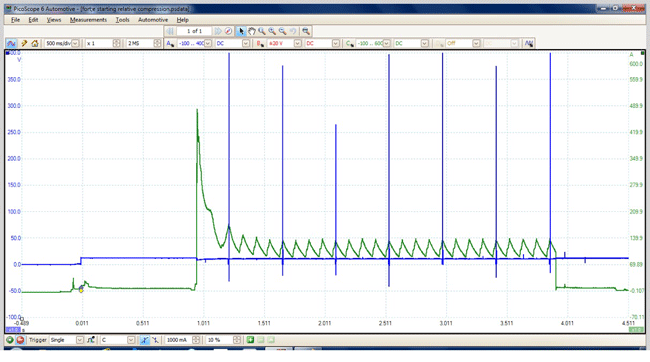
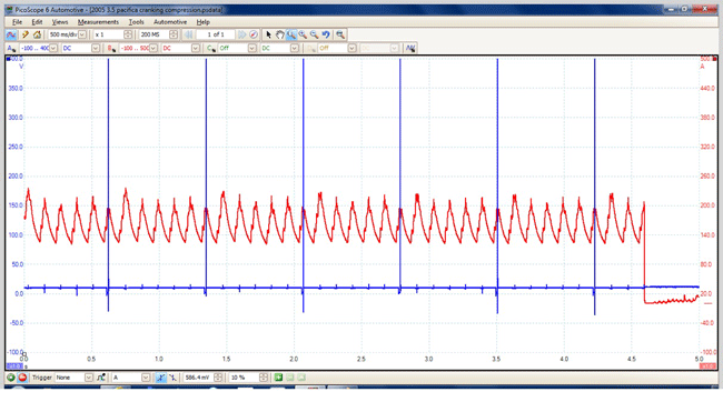
Posted By: Albert Hammond – Written By Pete Meier For years, I was amazed at how few technicians I worked with had ever used a scope, let alone owned one of their own. In every shop I’ve worked in over the last 20 years, I was it. But I’ve been pleased to see that scope use is on the rise, as evidenced by the number of techs who raise their hands in the presentations I make around the country and the growth of online support groups – even on Facebook! And no matter the reason for the growth, I’m glad that more and more of you are seeing just how valuable this diagnostic tool can be. Here are a few of my favorite uses for the scope. I hope you find them helpful. As a note before we get started, I am going to share the scope settings I use. I admit I am no “guru” in scope use and learn continuously from those that are. I’m sure there are many of you who can offer advice on even more efficient ways of setting up and performing these tests, and I hope you will – in the comments section on MotorAge.com! The relative compression test Many years ago, I was tracking down the cause of a slight misfire on a Chrysler minivan V6. After checking fuel and ignition, I found myself having to dive deeper into the mechanical health of the engine. All of you know how time-consuming performing a conventional cranking compression test on a transverse V6 can be, and I also checked cylinder leak down on all six at the same time! Needless to say, I spent a few hours on the job that I never did get paid for. The relative compression test is a way of assessing the overall health of the engine with a lot less trouble and in a matter of minutes, instead of hours. It is one test I perform on every engine that I find myself troubleshooting a drivability concern on. Scope settings: Channel 1 – High current clamp attached to either negative or positive battery cable. Scale set to read to at least 600 amps to capture initial inrush current expected. Channel 2 – Standard lead or secondary clamp attached to cylinder ignition source (coil or secondary lead). Choose cylinder that is easiest to access. Adjust voltage scale to match connection and be careful to use attenuator if needed. Time base – 500 milliseconds per division OR 5 seconds total screen time Trigger – Single capture with the trigger set to rising slope and +1 amp. These settings allow me to capture all the info I need on one screen, and to do so without worrying about starting or stopping the scope manually. As soon as I turn the key “on,” the scope will begin to capture data. Figure 1 shows an example of what you can expect to see.  

Figure 1

The green trace is the current pattern captured. The focus is on the repetitive sawtooth pattern, where each peak represents the amount of current it took to push a cylinder through its compression stroke. Even on my old UEI scope, I could distinguish as little as a 10 percent drop in an individual cylinder’s compression using this method. In this capture, the cylinders are uniform in appearance. But remember, this is a “relative” view, relative to all the other cylinders. If there is a mechanical issue that is causing low compression across the board, you’ll see a very similar picture, with only one noticeable difference – the current levels of the peaks will be lower than you’re used to seeing on a healthy engine. I can also see that ignition timing appears to be OK since the ignition reference is intersecting the current pattern on, or just before, the peak. The spark occurs just before TDC, right?  

Figure 2

Figure 3

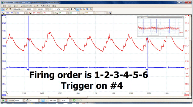
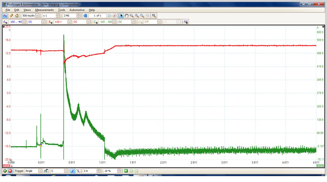
Take a look at Figure 2 for an example of a “known bad” capture. Though hiding behind the ignition reference, it is clear that the peak for that cylinder is not reaching the same level as the others. By following the firing order as shown in Figure 3, I know which cylinder I need to take a closer look at. With that information in hand, I have no problem going back to the customer and asking for the additional time I’m going to spend isolating the exact cause. Battery/charging system test A common reason I hear from techs who own (or have access to) a scope but don’t use it is the time it takes to set up. If you fall into that category, then let me ask you this. Don’t you turn the lights and coffee pot on every morning when you get to the shop? Don’t you start up the computer workstation you use so you can access your service information and workflow for the day? Starting up your scope should be on that same list of items, and if you use it to perform this next test on every car you get, you’ll also become more comfortable with the tool. A side benefit is that you’re performing a service for your customer that just might make you a little more money in the process. Scope settings: Channel 1 – Standard leads attached to battery positive and negative terminals. Scale set to read up to 2 volts per division or 0-20 volts total screen range. Channel 2 – High current clamp attached to either negative or positive battery cable. Scale set to read to at least 600 amps to capture initial inrush current expected Time base – 500 milliseconds per division OR 5 seconds total screen time Trigger – Single capture with the trigger set to rising slope and +1 amp. Figure 4 shows an example of a typical system test result. But for clarity, let’s break out the voltage and current patterns and review the key points individually.  

Figure 4

Figure 5

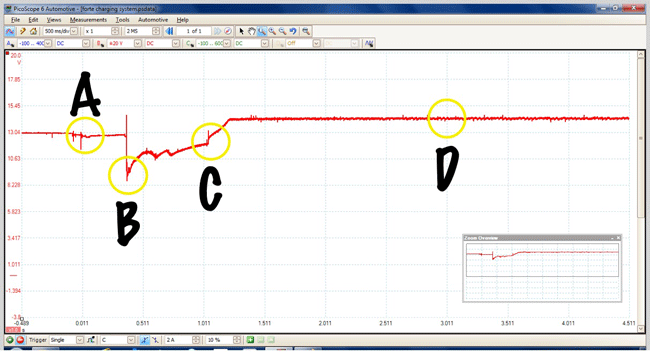
Figure 5 is the voltage alone. Just before “A” is the same Open Circuit Voltage you would read with your voltmeter, while “A” itself is the slight drop in voltage when I turned the key on. But I didn’t stop there, did I? I continued to the “Start” position and engaged the starter motor. “B” is the inrush voltage drop caused when the starter motor is just beginning to turn. After all, I have to get the starter moving and the starter is acting against all that mass in the engine. This loaded voltage reading is going to be lower than what you’re used to seeing when performing a conventionally loaded voltage test so rather than use the 9.5-9.6 limit you learned in school, use 8.5 volts as your minimum here. The time between “B” and “C” is the engine cranking. The little hills you can see are caused by the individual cylinders coming up on their compression stroke, just as we saw in the relative compression test. At “C”, the engine has started and is running on its own, with the key returned to the “Run” position. The upslope is the charging system replenishing the battery before settling on a more stable charging voltage at “D”. Now on Figure 6, the current pattern.  

Figure 6

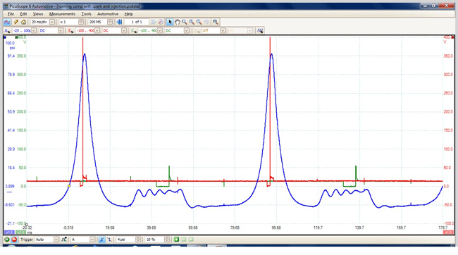
As we saw in the voltage pattern, “A” is where the key is turned on and the scope starts its trace. As the key passes to the “Start” position, current flows through the solenoid contacts and then into the starter motor. Again, the inertia of the starter motor and the engine have to be overcome before it will begin to move and that brings us to “B” – inrush current. In this example, inrush current is reaching nearly 600 amps! But it’s only for a microsecond and is not an indication of any problems in the system. By now, you recognize what the peaks represent on the way to “C,” or the time the engine starts running and the alternator starts putting back what the starting system took out. Notice the short but rapid increase in current that quickly drops off and becomes stable. Since the current clamp is around all of the negative (or positive) battery cables, the current graphed on the screen represents “net” current flow; that is, the final total of current demanded by the system and the current being supplied by the alternator. This net amount will run around 3 amps or so. Any significantly higher amount should be cause for further investigation and may indicate a sulfated battery that is placing a burden on the alternator. Running in-cylinder pressure diagnostic This is one test that I truly believe was groundbreaking, changing the way we test engine mechanical systems forever. By adding a pressure transducer to your scope, you can now “see” the pressure changes in a cylinder throughout the entire 720° engine cycle – and with no more effort that performing a cranking compression test with a mechanical gauge. In Figure 7, I’m showing you a normal cylinder with the ignition and injector events included for reference.  

Figure 7

Scope settings: Channel 1 – Pressure transducer is connected to channel 1. Follow the manufacturer specific set up instructions for your scope. On this Pico, the transducer scale is selected from a drop down menu and in this example is reading -25 to +100 psi. Channel 2 – Connected to ignition event based on ignition system used by the vehicle. Channel 3 – Connected to injector event, by back probing ground side (control side) of the injector and using a 10:1 attenuator to protect the scope from voltage overload. Scaling is -100 to +400 volts to allow for the inductive kick of injector that occurs on turn-off. Time base – 20 milliseconds per division OR 0.2 seconds total screen time Trigger – Set to “auto”, rising slope of channel 1 with capture to begin at 4 psi. While this capture was taken using the Pico WPS500 transducer, there are others on the market notably those offered by Snap-on and Automotive Test Solutions (ATS). I have to offer props to ATS and its head, Bernie Thompson because I sincerely believe he is the one most responsible for bringing this test method to the industry. There is so much information in this one capture that I can’t begin to do it justice in this short space but luckily, Bernie has written a series of articles on this technique for us and you can access them all on the website. But to whet your appetite, consider that this method can find problems with poorly sealing valves, variable valve timing issues, timing belts that are out of time, and a lot more – all without tearing anything apart for a visual check. Think that will save you time? Fuel system testing The pressure transducer can be used for a lot more than in-cylinder testing, too. One way I like to use it is to deploy it on my scope for monitoring fuel pressure in place of my mechanical gauge. It allows me a quick way to check for injector issues that otherwise would take a lot of time to test. But I’m getting ahead of myself. Let’s get to the settings I use to capture the patterns you see in Figure 8.  

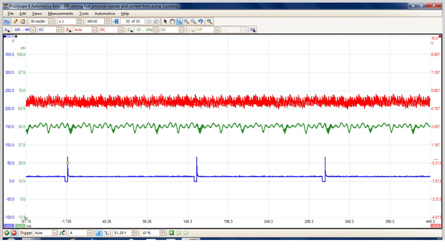
Figure 8

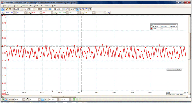
Scope settings: Channel 1 – Connected to injector event, by back probing ground side (control side) of the injector and using a 10:1 attenuator to protect the scope from voltage overload. Scaling is -100 to +400 volts to allow for the inductive kick of injector that occurs on turn-off. Channel 2 – Low current clamp wrapped around a “Fuse Buddy” that has been placed in substitute for the fuel pump power feed fuse in the junction box. Scale set to 0-10 amps. Channel 3 – Pressure transducer installed in fuel test port instead of a mechanical fuel gauge. Scale set to -25 to +100 psi. Time base – 50 milliseconds per division OR 0.5 seconds total screen time Trigger – Set to “auto”, rising slope of channel 1 with capture to begin at 50 volts. Testing fuel pump current has been around for as long as I’ve been using a scope but there are still lots of techs that have never heard of this technique before. The pattern shown is not clear enough for diagnostic use, so let’s take advantage of the scope’s ability to zoom in and take a look at the pattern shown in Figure 9. With very little effort we can see how much current the pump is drawing (a little more than 5 amps here) and what the speed of the pump is (roughly 5300 rpm). Consider that this approach works well on older style systems and you may have to adjust it a bit when looking at pumps that are pulse-width modulated. Even so, the pump is a motor, just like a starter motor, and it’s current will be impacted by the amount of work it’s doing – or not doing. And using this method beats banging on the fuel tank with a hammer!  

Figure 9

Consider a pump that has a low current draw and a high pump speed. That indicates a pump that isn’t working hard. Ever have a customer get towed in for a “no start” concern where his car said it had a half a tank of gas but it was really empty? How about the opposite scenario – where pump speed is low and current demand is high? That indicates a pump trying to overcome a restriction – maybe a clogged filter?  

Figure 10

On to Figure 10 for a closer look at the pressure transducer pattern. Notice the six lowest valleys between the injector events. We’re looking at a six-cylinder engine, and the injector pressure drops across all six injectors. How long would it take you to perform this kind of test conventionally? In this example, they all appear even so I don’t suspect a problem with a sticking injector. However, there are funny little squiggles on every other valley. What causes those, do you think? In this case, the three squiggle captures are all on the same bank and closest to the test port. This is normal “ringing” in the fuel line as each injector opens and closes. The rear are less so because the distance allows the rail to dampen the effect before it gets to the transducer. And No. 5 is… Actually, my fifth favorite test is any test I can perform with my scope that I haven’t tried before. The four examples I’ve provided are great examples of tests that once, had never been performed before! But some enterprising technician asked “What if?” and tried it. Now, they are all pretty standard for all of us! So ask yourself the next time you face a diagnostic challenge how you could apply your scope to the situation. And if you come up with something, let me know. I’d love to hear about it!
Article Source : http://www.searchautoparts.com/automechanika-chicago/commitment-training/five-ways-use-scope-diagnosing-vehicles?page=0,3
]]>

Car fanatics go wild for the SEMA Show

SEPTEMBER 16, 2015 BY ANDREW MROZINSKI

The annual SEMA Car Show is without question one of the biggest events on the motoring calendar, with petrol-heads flooding Las Vegas each year to take part in it. The show has been running since 1967 and the mixture of classic custom cars and strange sights makes iconic, with this year’s show being held in the Las Vegas Convention Centre in November.

It should be noted that the SEMA Show is an in-house event for those from the automotive trade, not an event that is open to members of the public, but this doesn’t affect attendance levels. As in previous years, the 2014 event drew more than 100,000 industry people from around the world to Las Vegas and the manufacturers showcasing vehicles ranged from the major US companies General Motors and Ford, to top brand names from around the world like Nissan, Toyota, Mazda, Honda, Hyundai, and Fiat-Chryslers Group (as you can see, Japan has a major influence on the event).SEMA_Custom_Cars

Although these big manufacturers showing off their hot new upcoming models represent a big part of the SEMA Car Show, it is not all there is to the event. As with previous years, the 2014 show featured guest appearances – including one by Miss HOT ROD Kristian Mill, who was showcasing her own custom-built Ford pickup and signing autographs. There were also a number of special events, including SEMA Ignited on November 7th, which is where the public get the chance to view the cool and crazy custom vehicles and shindigs like the Exhibitor Appreciation Party and the After-Party, which featured music from the likes Gary Clark Jr.

However, what most people will want to know about is the actual cars – the expensive, the rare and the mad. Amongst the classic rarities on a show this year was the Porsche 911 “277” showcased by Magnus Walker, who collects and modifies Porsches, and a 1967 Ford Mustang Fastback, in glorious condition and containing a powerful Ford Cobra V-8 engine. When it comes to the crazy customizations that are always a big part of SEMA, 2014 did not disappoint. The Badger Air Brush custom motorbike and the Kia Soul ice cream van containing speakers shaped like waffle cones and windows designed as blackboard menus were two of the strangest sights on show at the 2014 event.

Overall the SEMA show brought together lovers of classic cars and fans of sites like www.mobilecasinocanada.ca, for a week of motoring mayhem – with the casino heritage of Las Vegas making the perfect location – as car and casino fans both love life in the fast lane Sourcehttp://ridestory.com/2015/09/16/car-fanatics-go-wild-for-the-sema-show/#.WEN00BorKCh                                               source]]>

P1400 for Chevrolet

How to fix a P1400 Cold Start Emission Reduction Control System on Chevrolet If you have a P1400 Chevrolet trouble code, read this article on what the code means and how to fix the problem. OBD Code P0506 is the generic code for this problem. Basically, the code is triggered by dirty or bad components in the pathway leading to the intake or the vacuum system. Catalytic converters must be warm before they can work properly. On a cold start, the PCM provides a rich mixture to keep the cold engine running. All that extra fuel goes into the catalytic converter. But the exhaust isn’t very hot, because, ah, the engine is pretty cold. GM has employed several strategies to fire up the catalytic converter quicker and reduce cold start emissions. One way is to use a secondary air pump that pumps outside air directly into the catalytic converter. That method dumps extra oxygen into the converter to react with the extra fuel and burns it off. In the process, the converter heats up to normal temps. The second method is to adjust idle speed and spark timing. It’s this second method that can give you a P1400 Chevrolet trouble code. Specifically, when the PCM senses a cold start (any time an engine has been sitting for 3 or more hours) the PCM increases idle speed and retards spark timing. Then the PCM monitors all these values to calculate an exhaust energy model: Engine speed Spark advance Throttle position Engine airflow Engine coolant temperature Engine runtime Park/neutral position Vehicle speed In order to set the P1400 Chevrolet code, all these conditions must be met: A cold start has been detected. The vehicle speed is less than 2 km/h. The engine is at idle with no input from the accelerator pedal. The airflow per cylinder is greater than 80 mg/cylinder. DTCs P0101, P0102, P0103, P0106, P0107, P0108, P0112, P0113, P0116, P0117, P0118, P0120, P0121, P0122, P0123, P0220, P0222, P0223, P0201, P0202, P0203, P0204, P0205, P0206, P0300, P0335, P0336, P0351, P0352, P0353, P0354, P0355, P0356, P0502, P0506, P0507, P0601, P0602, P0603, P0604, P0606, P0607, P062F, P0641, P0651, P1101, P1516, P1682, P2101, P2119, P2120, P2122, P2123, P2125, P2127, P2128, P2135, P2138, P2176, P2610 are not set. This DTC runs for 15 seconds within the first 70 seconds of start up. This diagnostic runs once per trip when a cold start has been determined. If the actual exhaust energy model does not match the expected exhaust energy model the PCM will set a P1400 Chevrolet trouble code. In late model vehicles with an electronic throttle body, you should remove the throttle body and perform a complete cleaning of the throttle body bore and throttle plate. Do NOT simply spray throttle body cleaner into the throttle body. That is NOT the recommended procedure. Throttle body solvent can penetrate along the throttle plate shaft and enter the motor/gear area and damage the throttle body. Instead, spray the cleaner on a soft cloth and wipe the parts. When you’re done, perform a throttle body idle relearn procedure to reestablish base idle. Next, inspect the air filter and air duct along with these items: Modified, damaged, or restricted air cleaner box and duct Crankcase ventilation system for correct operation Vacuum leak and other un-metered air downstream of the mass airflow (MAF) sensor Intake manifold leak Damaged, restricted, modified or enhanced exhaust system Inspect the engine mechanical for items that could alter the air flow into the combustion chamber. Shops report that a throttle body cleaning, MAF sensor cleaning, and a new air filter usually solves the problem.]]>